SHOCK ABSORBER CONSTRUCTION
Bore Size
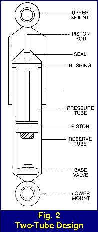
Bore size is the diameter of the piston and the inside of the pressure tube. Generally, the larger the unit, the higher the potential control levels because of the larger piston displacements and pressure areas. The larger the piston area, the lower the internal operating pressures and temperatures. This provides higher damping capabilities.
Valving
Ride engineers select valving values for a particular vehicle to achieve optimum ride characteristics of balance and stability under a wide variety of driving conditions. Their selection of valve springs and orifices control fluid flow within the unit, which determines the “feel” and handling of the vehicle.
Full Displaced vs. Rod Displaced Valving
Full displaced valving is a significant advance in shock absorber design and construction. It reduces internal operating pressures and aeration for greater damping capabilities. Full displaced valving also provides greater latitude in engineering how a shock will perform on a specific vehicle. A typical rod displaced shock has a total of eight valving stages:
A three-stage piston valve
A three-stage base valve
Two stages as the fluid passes through the piston
Full-displaced design allows ten stages by adding a blow-off valve and a dual rate piston replenishing spring.
In a rod-displaced shock absorber, control is generated with the fluid displaced by the rod, which goes through the base valve during compression. Fluid moving upward past the piston during the compression cycle does no significant work.
When a shock absorber with full displaced valving goes into a compression cycle, the fluid forced up through the piston is performing significant work – it’s a much more efficient shock absorber.

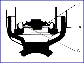
Full Displaced Base Valving
A. At slow piston rod speeds, fluid passes through a predetermined orifice area in the valve seat.
B. At medium rod speeds, fluid is controlled by discs, which act as flat blow-off springs.
C. At high speeds, fluid is controlled by the orifice slot areas in the valve plate.

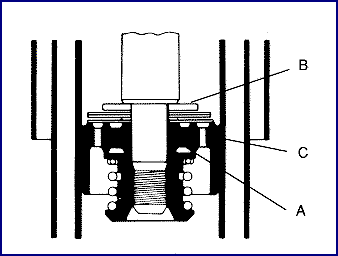
Piston Valve During Compression
A. At slow piston rod speeds, an orifice controls fluid flow.
B. At progressively faster rod speeds, the exclusive patented Monroe dual rate disc system provides two valving stages.
C. At very high piston rod speeds, orifice restriction controls fluid flow.

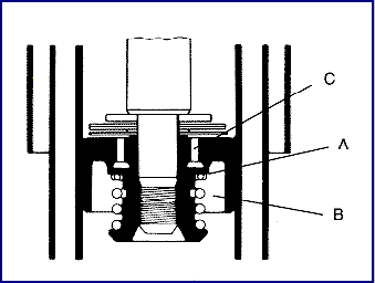
Piston Valve During Extension Cycle
A. At slow piston rod speeds, fluid is regulated by an orifice in the piston valve seat.
B. At medium rod speeds, fluid is controlled by the spring and thickness of steel discs.
C. At high speeds, inner passage restriction provides control.


